
What are Discharge Measuring Devices?
The devices and instruments used for the measurement of rate of flow or discharge of a fluid, are called Discharge Measuring Devices.
The quantity of the fluid flowing per unit of time across any cross section of a pipe or conduit, is called discharge or the rate of flow of fluid. The discharge of the fluid may be expressed as the mass of fluid flowing per second across any cross section of pipe or weight of fluid flowing per second across that cross section or volume of fluid flowing per second across that cross section of pipe.
Accordingly, the rate of flow may be expressed in units like (1) \text {kg} \ \text {s}^{-1} (2) \text {slug} \ \text {s}^{-1} (3) \text {m}^{3} \ \text {s}^{-1} (4) \text {lit} \ \text {s}^{-1} etc.
Various types of devices used for measurement of discharge are –
- Pitot Tube.
- Venturimeter.
- Orifice meter.
- Rotameter.
- Notches & Weirs.
These are explained below –
1. Pitot Tube
A pitot tube is an instrument to determine the velocity of flow \left ( v \right ) of flow at the required point in a pipe or stream. Thus, the discharge can be determined by a simple relation –
\text {Discharge (Q)} = \text {Cross sectional area (a)} \times \text {velocity of flow (v)}
A simple pitot tube consists of a glass tube bent through ( 90 \degree ) as shown in figure. The lower end of the tube faces the direction of the flow. The liquid rises up in the tube due to the pressure exerted by the flowing liquid.

By measuring the height ( h ) of rise of liquid in the tube, we can find out the velocity of the liquid flow by using the relation \quad v = \sqrt {2gh}
Thereafter discharge is calculated by using the relation \quad Q = \left ( a \sqrt {2gh} \right )
2. The Venturimeter
A venturimeter is an apparatus meant for measuring the flow quantity or discharge of a liquid flowing through a pipeline. It works on the principle of Bernoulli’s theorem.
Simplest form a venturimeter is consists of following three sections –
- Convergent cone.
- Throat.
- Divergent cone.
Construction and working principle of a venturimeter is shown in figure below.

The liquid flowing through the venturimeter is accelerated between the sections 1 and 2 of the convergent cone. As a result, the velocity of liquid at section 2 increases. This increase in velocity results in decrease in pressure at section 2.
The liquid is again decelerated between the sections 2 and 3 in the divergent cone. As a result of this retardation the velocity of liquid decreases which consequently increases the pressure at section 3.
To avoid the tendency of separation of liquid from the walls of venturi (1) in th convergent cone, the ratio of diameter of throat and the diameter of pipe is kept fixed ranging between \left ( \frac {1}{3} \right ) to \left ( \frac {1}{2} \right ) . (2) in the divergent cone the length is made sufficiently longer about 3 \text {to} 4 times longer than the convergent cone.
A Piezometer or U-Tube manometer is connected to measure the difference of pressures \left ( h \right ) between sections 1 and 2.
The working of Venturimeter is based on Bernoulli’s theorem and equation of continuity. Relation used for measurement of discharge is given below.
Q = \left [ \frac {C_d a_1 a_2}{\sqrt {a_1^2 - a_2^2}} \right ] \sqrt {2 g h}
= C_d \left [ \frac {a_1}{\sqrt {K^2 - 1}} \right ] \sqrt {2 g h}
3. Orifice Meter

An orifice meter is used to measure the liquid discharge flowing through a pipeline. It also works on the principle of Bernoulli’s theorem.
An orifice meter, in its simplest form is consists of a plate having a sharp edged circular hole known as an orifice. This plate is fixed inside a pipe as shown in figure.
A mercury manometer is inserted to know the difference of pressures \left ( h \right ) between the sections 1 and 2 of pipe. Relation used for measurement of discharge is given below.
Q = \left [ \frac {C_d a_1 a_2}{\sqrt {a_1^2 - a_2^2}} \right ] \sqrt {2 g h}
4. Rotameter
Rotameter is used as a discharge gauging device which gives direct reading of discharge.
It consists of a float which hosed within a transparent tapering vertical tube introduced in the pipe line. The flow of liquid being upwards as shown in figure.
The float is made of a material denser than the fluid passing through the Rotameter tube. The float is free to rise in the tube and its position is a function of the rate of flow. A calibration scale is marked on the transparent tube in units of the rate of flow or discharge.
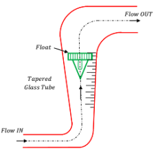
To provide stability to the float, it is provided with slanting slots at the upper end due to which it keeps on rotating about its vertical axis remaining in the central position.
Though, Rotameter gives direct reading of discharge, following relation can be used for its calculation –
Q = C_d A \sqrt { 2gh }
In this expression –
- C_d is the coefficient of discharge which lies between 0.7 to 0.75
- A is annular area between the tapering pipe and the top of the float.
- h is the effective head across the float. So, h = \left ( \frac {\text {Volume of float}}{\text {Area of float}} \right ) \times \left ( S - 1 \right )
- S is the Specific gravity of the float material and \left ( S - 1 \right ) is called effective specific gravity of float.
5. Notch & Weir
A notch means an extended opening provided at side of a tank which extends even above the free water level surface of liquid in the tank. It is thus a large orifice having no upper edge.
A notch is used to measure the flow of water or discharge from a tank.
A weir is also a notch but it is made on a large scale. It is a notch cut in a dam to discharge the surplus quantity of water. The stream of water discharged by an orifice is called a jet whereas the sheet of water discharged by a notch or weir is called a nappe or vein. The upper surface of the notch or weir over which the water flows is called the Crest or Sill.

According to the shape, notches may be of following types –
- Rectangular notch or weir.
- Triangular notch or weir.
- Trapezoidal notch or weir.
According to the purpose, notch or weir is classified into two types –
- Waste weir – It is used for discharging the surplus quantity of water from a reservoir.
- Gauging weir – It is provided for gauging the discharge from a reservoir.
A Rectangular Gauging Weir is shown in figure. The head of water ( h ) over the weir is measured. The discharge over the weir can now be determined.
Discharge formulae for various weirs are given below –
- For a rectangular weir \quad Q = \frac {2}{3} \ C_d \ l \ \sqrt {2 g} \ {H}^{\frac {3}{2}}
- For a trapezoidal weir \quad Q = \frac {2}{3} \ C_d \ \sqrt {2 g} \ {H}^{\frac {3}{2}} \left [ \frac {2}{3} \ l + \frac {8}{15} \tan \theta . H \right ]
- For broad crested weir \quad Q = 1.705 \ C_d \ l \ {H}^{\frac {3}{2}}
- For Ogee weir \quad Q = 2.20 \ l \ {H}^{\frac {3}{2}}